TSV05 / Pertec
TSV05_Maint.pdf TSV05_User.pdf
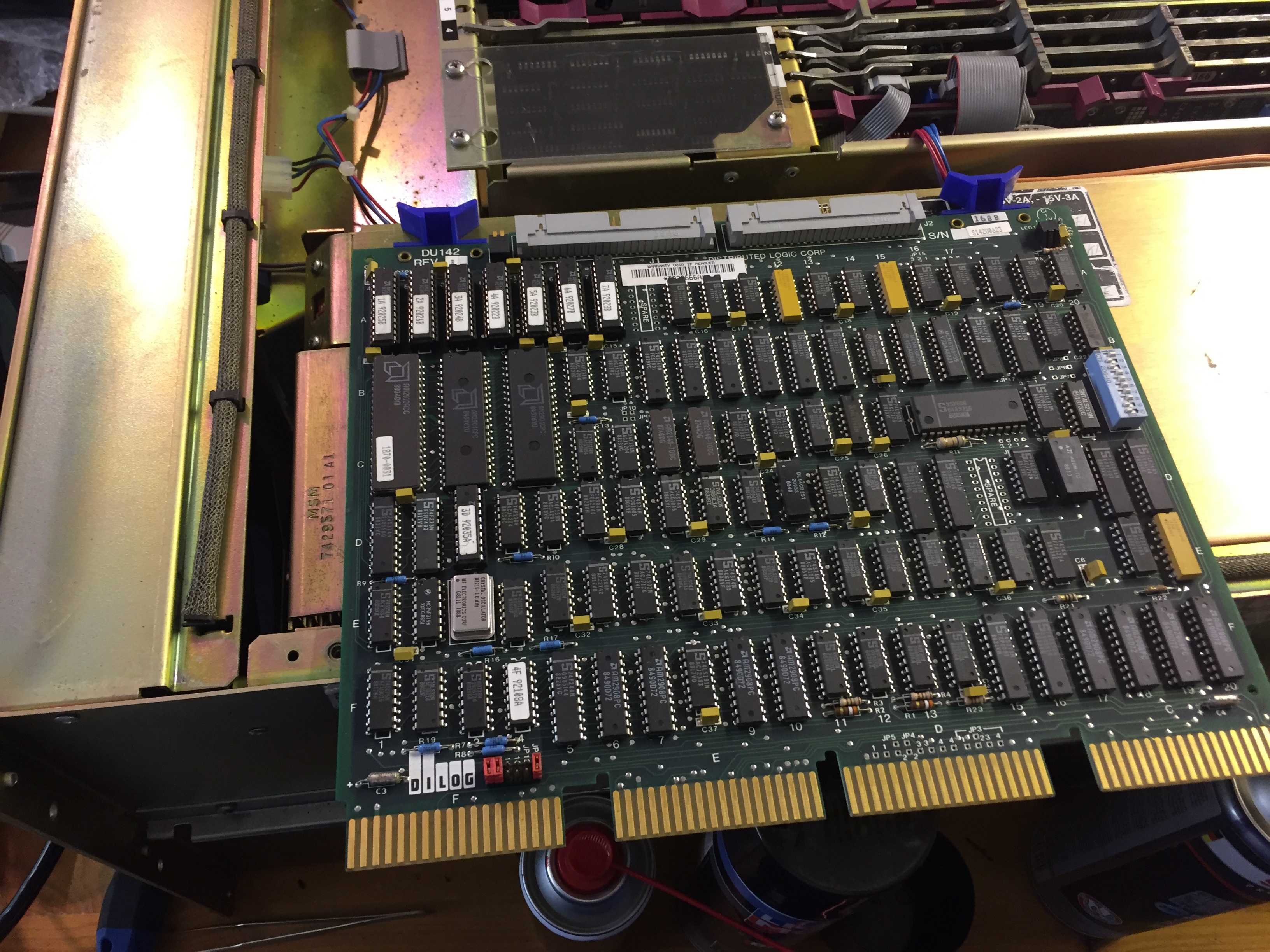
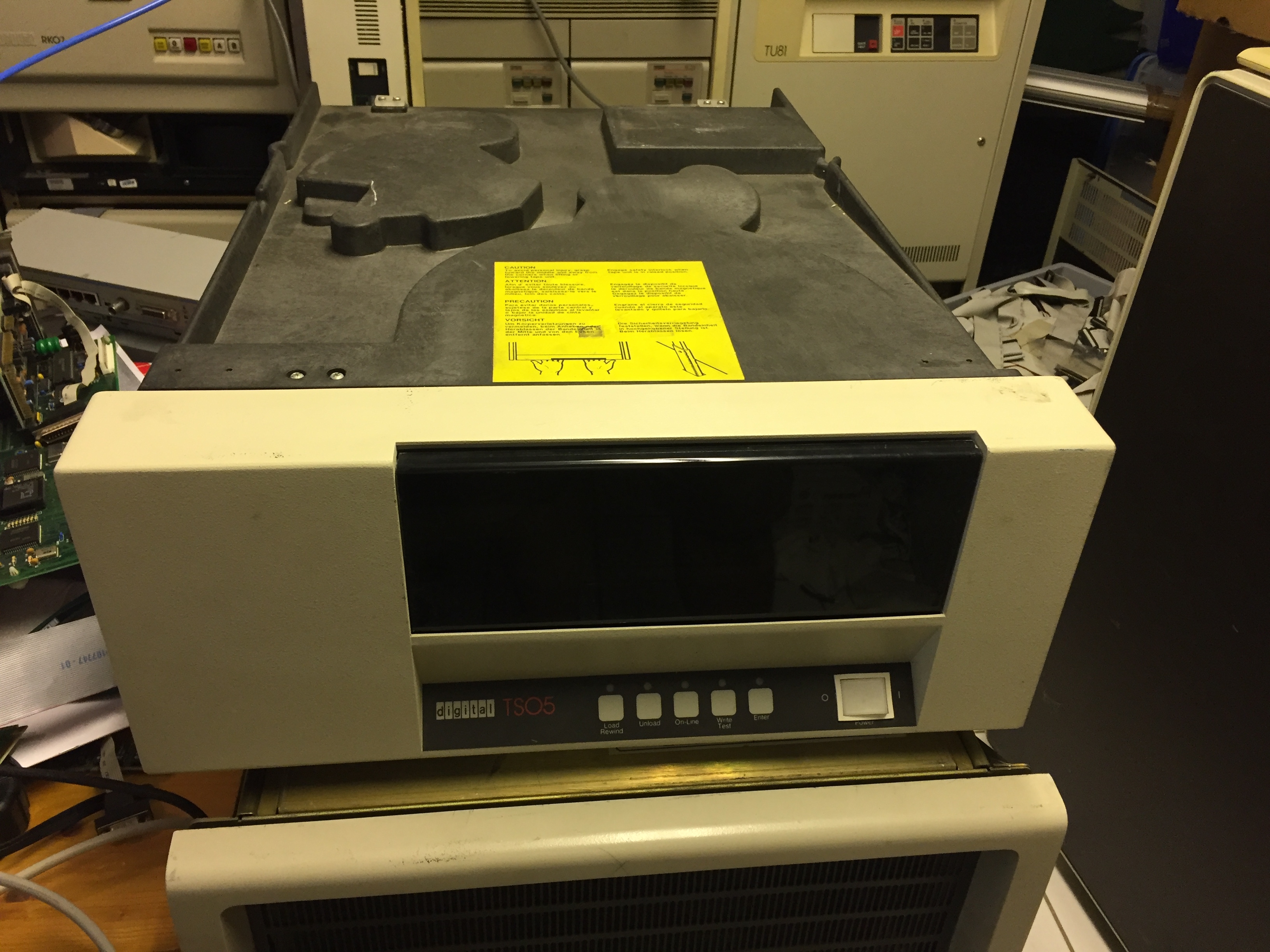
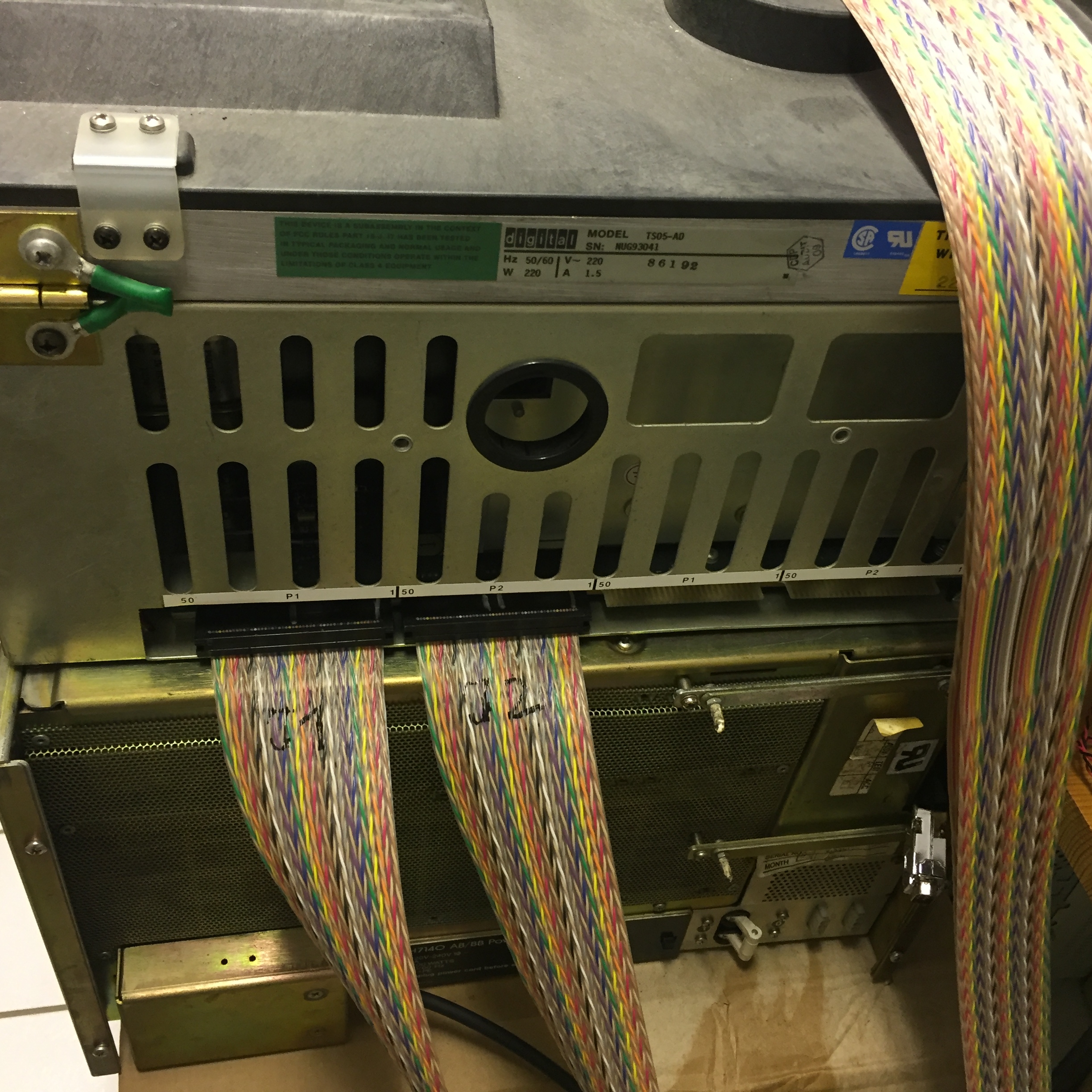
After I have managed to get RT-11 installed, the time is come, to look at my new Dilog DU-142 Pertec (TS11 compatible) controller, and the DEC TS05 (Cipher F880) 9-Track Tape drive.
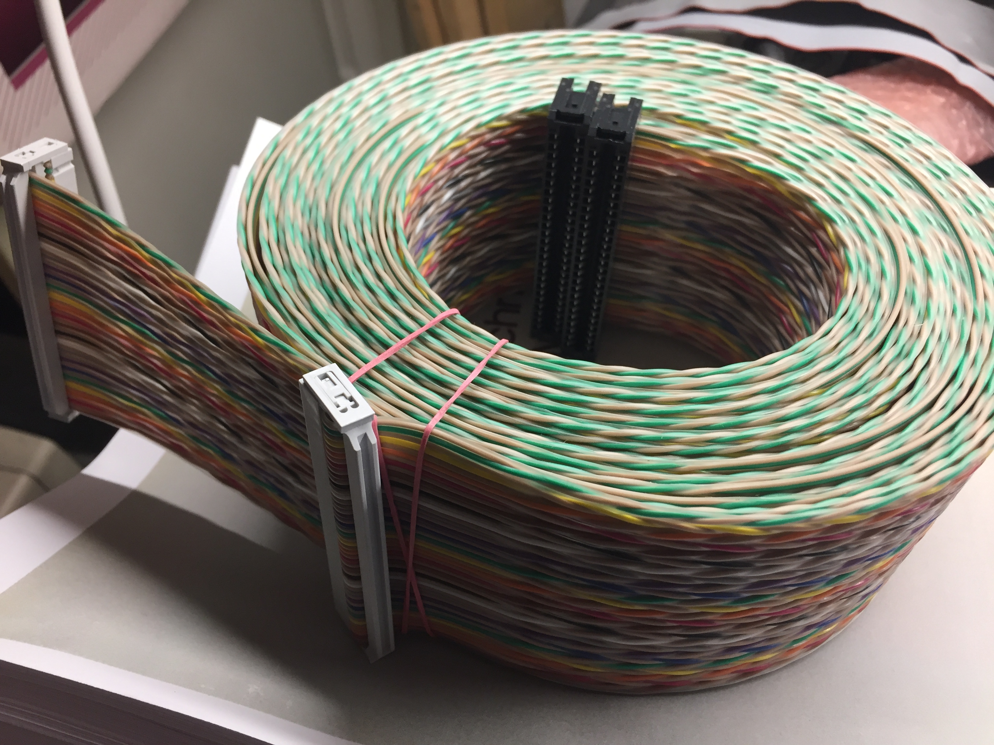
Don’t spend too much time to find the mostly missing Pertec Cables, build them by you own (but do it right!)! It’s quite easy, when you have the 50 Pin Edge connector. (google is your friend)
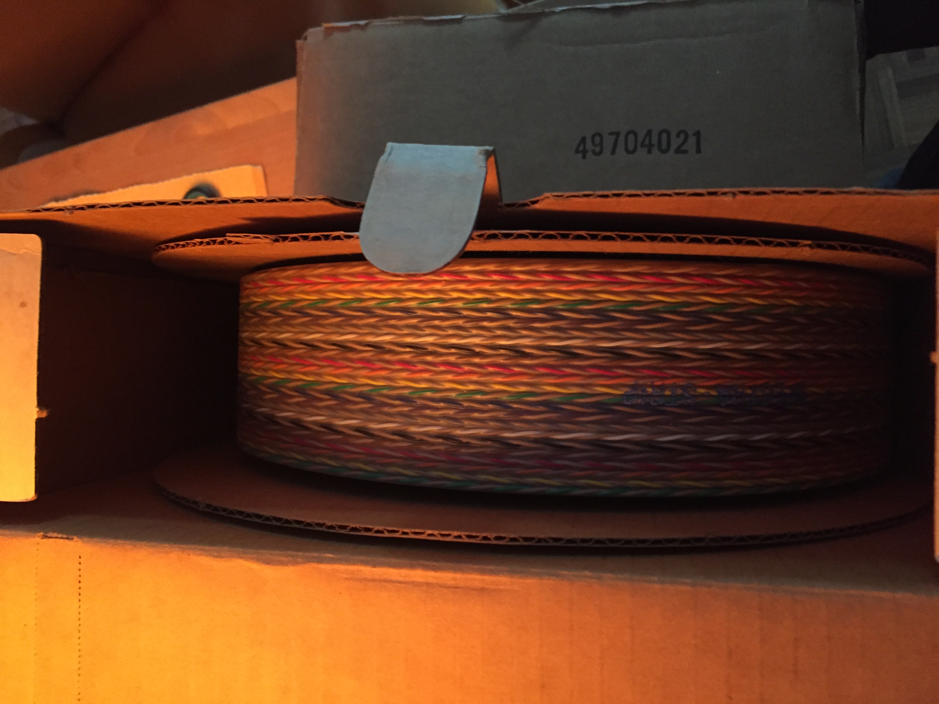
As I like the old style, I have bought an original Spectra-Strip Cable NOS from 1979. And it fits quite good. A shielded cable would be better I think, but they are so much expensive, that I was not willing to pay for them.
show dev shows, that rt11 has recognized the Dilog without reconfiguring anything -strange I was a bit prepared for my first sysgen session.
.show de:ms

Device Status CSR Vector(s)
------ ------ --- ---------
 MS Installed 172522 224 300
After this, I have started a short test, to see, if my drive reacts on any OS command.
.init/bad ms0:
MS0:/Initialize; Are you sure? Y
.
As soon as I have pressed „Y“ the drive began to turn. Good sign.
Now I was interested to create RT-11 Distribution Tapes, which looks like is quite simple, here is the procedure out of the DOC (side 5-8):
.assign ms0: KIT:

.assign du0: BIN:

.@msb

.$Load Bin,Kit

.$Ini/Que/Vol/File:Bin:MBOT16.BOT Kit:
MS0:/Initialize; Are you sure? Y
Volume ID? RT5.4G
Owner? DIS MS 1/2

.$Cop Bin:MSBOOT.BOT Kit:/Pos:-1
 Files copied:
BIN:MSBOOT.BOT to KIT:MSBOOT.BOT

.$Cop Bin:MDUP.AI Kit:/Pos:-1
 Files copied:
BIN:MDUP.AI to KIT:MDUP.AI
........
........
........
.$Cop Bin:MSCPCK.SAV Kit:/Pos:-1
 Files copied:
BIN:MSCPCK.SAV to KIT:MSCPCK.SAV

.^C

.$Ini/Que/Vol/File:Bin: Kit:
MS0:/Initialize; Are you sure? Y
Volume ID? RT5.4G
Owner? DIS MS 2/2

.$Cop Bin:TRANSF.TSK Kit:/Pos:-1
 Files copied:
BIN:TRANSF.TSK to KIT:TRANSF.TSK

.$Cop Bin:TRANSF.EXE Kit:/Pos:-1
 Files copied:
BIN:TRANSF.EXE to KIT:TRANSF.EXE
......
......
......
.$Cop Bin:INDEX.IMG Kit:/Pos:-1
 Files copied:
BIN:INDEX.IMG to KIT:INDEX.IMG

.$Cop Bin:INDEX.IDX Kit:/Pos:-1
 Files copied:
BIN:INDEX.IDX to KIT:INDEX.IDX

.^C

.$Unload Bin,Kit
And now the trouble began.
To boot from TS11/TS05/TU80 you need to type or toggle in the Bootstrap or you are in a lucky situation where you have the matching BPROM for an M9312.
I’m in a not so bad position, as my PDP-11/84 has the possibility, to add own BootStraps to the EEprom which can be added via the setup menu.
So this was the first time, I have added an „own“ BootStrap and I have needed about 7 tries until I had it once correct typed in. But nothing happens, except the following message, which came instantly up.
Type a command then press the RETURN key: B MS0
Trying MS0
001120
I had no clue what this means, except, that this was not the outcome I was expecting!
After some more verification, like jumper settings, read write to tape, and so on I have decided to post it to cctalk, to find someone with detailed knowledge about.
http://www.classiccmp.org/pipermail/cctalk/2017-August/037014.html
Short after I have posted the bootstrap out of the Dilog Manual and the error I had, the first two replays with useful tips, explanations, and a deep understanding about these magic Assembler/MACRO stuff came in.
Jerry and Paul, were more than helpful, both have analysed the problem remotely, and found an issue in the printed Bootstrap of the Dilog Controller, which I would never had found.
In short words, it looks like the printed Bootstrap was after never tested > nice work! I through such pitfalls are a sign of today’s docs, but OK, I have learned, that this seams to be not the case.
Here are the addresses and values, who needs to be changed, to fix the Bootstrap loader of the Dilog DU142:
001020/001064
001030/001104
001040/001104
001050/100421
Here is the complete Bootstrap, like it is now saved to the PDP-11/84 EEPROM:
Device name = MS New =
Beginning address = 001000 New =
Last byte address = 001400 New =
Start address = 001000 New =
Highest Unit number = 1 New =
Device Description = TSV05 New =
Enter ROM ODT

xxxxxx/ = open word location xxxxxx if address even, byte if odd
RETURN = close location
. or LF = close location and open next
- = close location and open previous

ROM ODT> 001000/012700
ROM ODT> 001002/172520
ROM ODT> 001004/012701
ROM ODT> 001006/172522
ROM ODT> 001010/005011
ROM ODT> 001012/105711
ROM ODT> 001014/100376
ROM ODT> 001016/012710
ROM ODT> 001020/001064
ROM ODT> 001022/105711
ROM ODT> 001024/100376
ROM ODT> 001026/012710
ROM ODT> 001030/001104
ROM ODT> 001032/105711
ROM ODT> 001034/100376
ROM ODT> 001036/012710
ROM ODT> 001040/001104
ROM ODT> 001042/105711
ROM ODT> 001044/100376
ROM ODT> 001046/005711
ROM ODT> 001050/100421
ROM ODT> 001052/012704
ROM ODT> 001054/001102
ROM ODT> 001056/005000
ROM ODT> 001060/005007
ROM ODT> 001062/046523
ROM ODT> 001064/140004
ROM ODT> 001066/001074
ROM ODT> 001070/000000
ROM ODT> 001072/000010
ROM ODT> 001074/001116
ROM ODT> 001076/000000
ROM ODT> 001100/000016
ROM ODT> 001102/000000
ROM ODT> 001104/140001
ROM ODT> 001106/000000
ROM ODT> 001110/000000
ROM ODT> 001112/001000
ROM ODT> 001114/000000
ROM ODT> 001116/000000
So now all could be good, if I had not build the cable by my own …
With this changes it should be possible, to boot the RT-11 Tape, but I get the following error.
Type a command then press the RETURN key: B MS0
Trying MS0
001116
@
Paul and Jerry have debugged this remotely, and I have provided what was requested. Both were able to map this issue to a read Parity error.
Here the procedure:
Examine TSSR: @17772522/100210

Examine 1116 +7:

@001116/100022
@001120/000012
@001122/000000
@001124/000310
@001126/000001
@001130/100000
@001132/000000
@001134/000000
Extended Status 0 at 001124 seams to be OK, as 000310 can be mapped to: motion, on-line, phase-encoded drive
Extended Status 1 at 001126 seams to be not OK, as 1 means read data Parity error
The next suggestion was to read from tape (which was working some days before) and surprise I get the following output:
.dir ms0:
?DIR-F-Error reading directory

COPY MS0: NL:
?PIP-F-Directory input error MS0:
So the extended Status 1 makes sense, as reading was no longer possible.
I have checked again the drive, the coupler, the voltages, … All OK, next Morning I have started to check the cables, and surprise, I found overall three lanes without contact, or with changing state, depending on cable movement.
The following Lanes were affected:
Connector P1: 14
Connector P2: 8, 32
The real Issue was maybe P2:8 as in the Doc you will find the following description: Read data bit 7 (LSB!)
After this was fixed the drive works as expected means read/write and boot from it works.
.dir ms0:

MDUP .AI 56 MDUP .MM 56
MDUP .MS 56 MDUP .MT 56
MDUP .MU 56 SWAP .SYS 27
RT11AI.SYS 81 RT11PI.SYS 95
RT11BL.SYS 78 RT11SJ.SYS 79
RT11FB.SYS 93 RT11XM.SYS 107
...
...
...
LDX .SYS 8 LPX .SYS 2
LSX .SYS 5 MMX .SYS 10
MSX .SYS 11 MTX .SYS 9
MUX .SYS 16 NCX .SYS 9
NLX .SYS 2 NQX .SYS 7
ERROUT.SAV 18 MSCPCK.SAV 3
 122 Files, 2633 Blocks
Message 04 Entering Dialog mode

Commands are Help, Boot, List, Setup, Map and Test.
Type a command then press the RETURN key: B MS0


Trying MS0MSBOOT V05.04
▒*
So again many thanks to Paul and Jerry for their help, time and patience!